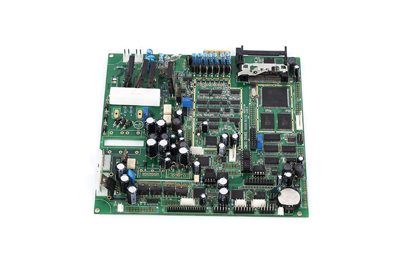
Printed Circuit Board is produced using electronic printing technology to connect electronic components. It is an important support for electronic components. Through the designed circuit schematic diagram, the circuit board is manufactured processed and then tested to ensure that the function and performance of the circuit meet the design and requirements. Finally, optimize and improve based on the test results to improve the reliability of the circuit board. It seems easy to make a printed circuit board, but it is not very simple to make a good one. It involves complex links and many details. So every step requires an experienced PCB design team and the PCB manufacturer does the job. Therefore, we discuss in detail how to create a perfect circuit board, from design to implementation.
When designing a PCB, the first task is to clarify the design goals. Design targets may include but are not limited to ordinary PCB boards, high-frequency PCB boards, Edge Plating PCB, Plated Half Holes PCB, Gold Fingers PCB, etc.
● Ordinary PCB, consider the layout and wiring to be reasonable and neat to ensure that the mechanical dimensions are accurate.
● High-frequency PCB boards, require special considerations to ensure the stability and anti-interference ability of signal transmission.
● Edge Plating PCB, pay special attention to the edge copper plating process to improve connectivity and reliability.
● Special types of PCB boards, such as Plated Half Holes PCB and Gold Fingers PCB, also need to consider their special process and design requirements.
In addition to the types listed above, other related factors need to be considered, such as the number of layers of the PCB, mechanical strength, etc. The choice of the number of layers directly affects the complexity and power consumption distribution of the circuit, while the mechanical strength is related to the stability and reliability of the entire device.
Before formulating a PCB design plan, the design goals must be fully considered and clarified to ensure the rationality and practicality of the design.
After the circuit board design plan is clear, an experienced PCB design engineer is needed to complete the schematic diagram. According to the schematic diagram, determine the physical size and number of layers of the PCB, and draw the block diagram of the PCB.
This step involves PCB the size, shape, layer layout, etc., After confirming that it is correct, convert the schematic diagram into a PCB layout and draw the connection lines in the PCB layout. This includes drawing wires, traces of the printed circuit board, ground wires, power lines, etc. At the same time, optimize the PCB layout, which includes adjusting component locations, signal paths, ground wires, and power lines, etc., to ensure that the layout meets design specifications, manufacturing requirements and performance indicators. Finally, PCB manufacturing files are generated, such as Gerber files, drilling files, BOM (bill of components), etc., and tested and verified.

Select appropriate components according to PCB design requirements and purchase them.
(1 )Parameters of components: Whether capacitance, resistance, inductance, operating frequency, etc. meet the design requirements and circuit functions
(2 )Placement of components: Closely related components are placed close together to reduce the length of the signal transmission path and reduce signal interference and crosstalk;
● Separately layout components with high power signals and small signals to reduce the interference of power signals to small signals;
● Consider the mechanical size and socket location of the PCB to ensure component layout does not affect the mechanical structure and socket installation
● For components that require heat dissipation (such as power amplifiers, voltage regulators, etc.), arrange heat sinks appropriately and ensure smooth heat dissipation paths.
● Taking into account future testing and maintenance needs, enough space should be left during the layout to facilitate the connection of test instruments and the replacement of components.
(3) Procurement of components: Cooperate with suppliers to select and purchase reliable components to ensure the quality and supply stability of components.
Send the PCB layout file to the PCB manufacturer. Once the PCB manufacturer receives the PCB layout file, they will use these files to produce the PCB board, including process steps such as manufacturing the PCB board, drilling, component mounting, and welding.
· Manufacturing Substrate: According to the PCB layout file, a layer of copper foil is coated on the fiberglass substrate, and then the circuit pattern on the PCB is formed through process steps such as photolithography and etching.
· Drilling: Use a drilling machine to drill holes in the PCB board to install components and connect circuits between different layers.
· Electroplating: Through the chemical plating process, a thin layer of metal is deposited on the surface of the copper foil on circuit board to enhance the corrosion resistance and weldability.
· Apply Solder Paste: Apply a layer of solder paste to the pad part of board to form solder joints when soldering components.
· SMT: Use an automatic SMT machine to accurately attach surface mount components to the pads of the PCB board.
· Plug-in: Insert plug-in components (such as DIP components) into sockets on the PCB board manually or using plug-in equipment.
· Reflow soldering: Send the PCB with components installed into the reflow oven. By heating the solder paste in the reflow soldering furnace, the solder paste melts and the components and PCB board are welded together.
· Wave soldering: For some components or specific requirements, the wave soldering process can be used to solder the components to the PCB board in the wave peak of liquid solder through the bottom of the PCB board.
Inspection and test the assembled PCB to ensure that the function and performance of the circuit meet the design requirements. Testing involves electrical testing, functional testing, environmental testing, etc. to ensure the reliability and stability of the PCB under various working conditions.
Once testing is complete, the PCB may need to be optimized and improved based on the test results and feedback. This may include modifying component layout, optimizing routing, adjusting component parameters, etc. Through continuous testing, optimization and improvement, a high-quality PCB that meets the design requirements can finally be obtained.

In the process of creating a perfect PCB circuit board, SCSPCBA has gone through many key steps such as design, layout, manufacturing, and testing. From the initial design concept to the final implementation, every step requires careful planning.
Careful design and reasonable layout are inseparable from teamwork and communication and collaboration, to ensure the performance and reliability of the circuit.
The close cooperation between design engineers, PCB designers, manufacturers and testers creates high-quality PCB circuit boards for SCSPCBA. At the same time, continuous optimization and improvement are also key factors for SCSPCBA's success in completing high-quality PCB and assembly.
In the process of realizing and pursuing more perfect PCB circuit boards, SCSPCBA will continue to uphold the pursuit of quality excellence, respect for customer needs, adhere to the concept of "quality first, customer first", and strive to provide customers with high quality, high-reliability products, and services.
Contact us for your one-stop solution for PCB and PCBA