In PCB design, the PCB drilling is a critical step. Proper PCB board technology and best practices can ensure the quality and reliability of PCB boards. However, people often encounter some problems in the PCB process, such as hole quality defects, hole diameter deviation, hole wall burrs, etc. To help you avoid these problems and improve your work efficiency, this article will introduce the considerations and best capacities for PCB drilling. We will discuss the classification of PCB drilling, the characteristics of PCB drilling, which stage of the PCB fabrication process, issues that need to be considered when drilling PCB, common drilling problems and their solutions, etc. Whether you are a beginner or an experienced PCB designer, this article will provide you with valuable guidance and advice to ensure you achieve excellent results in your PCB throughput process.
PCB drilling technology is a manufacturing process for drilling holes in printed circuit boards. During the manufacturing process, holes are created in the PCB to allow components to be mounted and circuit connections to be made. Through drilling technology, holes can be drilled at different locations on the surface and interior of the PCB to meet the installation needs of different components, different circuit layouts and design requirements. The size and location of drill holes are usually determined by design requirements and PCB layout.
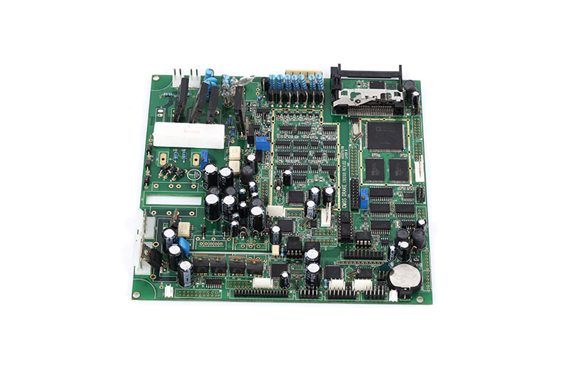
During the PCB drilling process, due to the accuracy requirements, SCSPCBA is usually completed using a mechanical drill or laser drill. Mechanical drilling machines drill holes by rotating the drill bit and controlling the descent of the drill bit. The laser drilling machine completes drilling by irradiating the PCB with a laser beam, which has higher accuracy and efficiency. The minimum laser drilling hole diameter of SCSPCBA is 0.1mm and the maximum is 0.15mm.

PCB drilling can be divided into many types according to different classification standards, each type has its own unique characteristics.
- Principle: Mechanical drilling is the process of gradually processing holes through a rotating mechanical drill bit.
- Applicability: Suitable for general hole processing, especially for larger diameter holes.
-Materials: Suitable for common rigid substrate materials such as FR-4, rated for 800 shots, Rogers high-frequency materials are generally more fragile and have a higher density which may result in reduced mechanical drill bit life. The working principle of mechanical drilling involves rotating tools, which on dense and hard materials can cause faster wear and shorten the life to 200 times. If the PCB manufacturer ignores this, it can lead to pitted holes. This results in the circuit board being scrapped.
- Accuracy: Generally higher accuracy, but for smaller diameter holes additional processes may be required to improve accuracy.
- Cost: Relatively low, suitable for mass production.
- Precautions: If PCB manufacturers deal with PCBs of high density and special materials, they need to pay attention to the life of the mechanical drill bit to prevent problems such as sinkholes. In this case, it may be necessary to regularly replace the drill bit or take other measures to ensure hole quality and processing accuracy.
- Principle: Laser drilling is a non-contact process that uses a laser beam to ablate PCB material to form holes.
- Applicability: Suitable for applications requiring high precision and small diameter holes, such as high-density interconnect PCBs.
- Materials: Suitable for a variety of PCB materials, including rigid and flexible substrates.
- Accuracy: High precision, especially suitable for the production of tiny holes.
- Cost: Relatively high, suitable for applications that require higher precision, usually for sample production or small batch production.
The PCB board with only one layer of drilling is suitable for simple circuit design and has a low cost.
It requires drilling holes on a multi-layer PCB board, which is suitable for complex circuit designs, but the cost is relatively high.
The drilling size is small, generally less than 0.2 mm, which is suitable for the drilling needs of high-density printed circuit boards.
The drilling size is larger, generally larger than 0.2 mm, which is suitable for the drilling needs of larger-sized PCB.

Drilling is often an early stage in the PCB manufacturing process but is a critical step in the overall process that directly affects the performance and quality of the final PCB.
The following are typical locations for drilling holes during PCB manufacturing:
PCB designers will design circuit diagrams and route them, determining the location of connectors, components, and the location of required holes.
Hole machining is usually done after the circuit diagram and wiring are completed on the PCB board. At this stage, the required holes are machined on the PCB board by mechanical drilling or laser drilling.
After hole processing is completed, the next steps usually involve coating, exposure, etching and other processes to form a copper foil layer and form the required circuit pattern.

Drilling technology plays an important role in PCB manufacturing, but you may encounter some common problems during the operation. Here are some common problems and solutions:
- Possible reasons: mechanical drill bit wear, insufficient laser power, high hardness of the substrate material, etc.
- Solution: Regularly replace mechanical drill bits, adjust laser power, select appropriate drill bits and processing parameters.
- Possible reasons: positioning error, fixture problem, mechanical vibration, etc.
- Solution: Check the positioning system of the mechanical equipment to ensure that the fixture is correct and reduce mechanical vibration.
- Possible reasons: tool wear, mechanical system problems, incorrect processing parameters, etc.
- Solution: Regularly replace cutting tools, check and adjust mechanical systems, and optimize processing parameters.
- Possible reasons: unstable tool or laser power, substrate material problem.
- Solution: Stabilize process parameters and ensure that the tool or laser system is in good condition.
- Possible reasons: The chips are not removed and the process parameters are inappropriate.
- Solution: Adjust tool design, improve cleaning process, and appropriately adjust processing parameters.
- Possible reasons: The material is hard and the cutting parameters are inappropriate.
- Solution: Choose appropriate tool materials and optimize cutting parameters.
- Possible reasons: The laser power is too high and the processing speed is too slow.
- Solution: Adjust laser power and processing speed to avoid overheating.

| SCPCBA PCB Drilling Capabilities | Drilling Process | Process Capability |
| 0.1/0.15/0.2mm mechanical drilling maximum plate thickness | 0.8mm/1.5mm/2.5mm | |
| Laser drilling hole diameter is the smallest | 0.1mm | |
| Laser drilling hole diameter is the largest | 0.15mm | |
| Mechanical hole diameter (finished product) | 0.10-6.2mm (corresponding to drill bit 0.15-6.3mm) | |
| The minimum finished hole diameter of the PTFE material (including mixed pressure) plate is 0.25mm (corresponding to the drill bit 0.35mm) | ||
| Mechanical buried blind hole diameter ≤0.3mm (corresponding to drill bit 0.4mm) | ||
| The drilling diameter of the green oil plug hole in the plate hole is ≤0.45mm (corresponding to the drill bit 0.55mm) | ||
| The minimum hole diameter is 0.35mm (corresponding to 0.45mm drill bit) | ||
| The minimum diameter of the metallized half hole is 0.30mm (corresponding to the drill bit 0.4mm) | ||
| The through-hole plate has the largest thickness-to-diameter ratio | 20:1 (excluding tool diameter ≤0.2mm; >12:1 needs evaluation) | |
| Laser drilling depth with the largest aperture ratio | 1:1 | |
| Mechanically controlled depth drilling of blind holes has the largest depth-to-aperture ratio | 1.3:1 (aperture ≤ 0.20mm), 1.15:1 (aperture ≥ 0.25mm) | |
| Mechanically controlled depth drilling (back drilling) has the smallest depth | 0.2mm | |
| Drilling - minimum distance from mechanical drilling to the conductor (non-buried blind hole plate and first-order laser blind hole) | 5.5mil (≤8 layers); 6.5mil (10-14); 7mil (>14 layers) | |
| Drilling - minimum distance from mechanical drilling to the conductor (mechanical buried blind hole plate and second-order laser buried blind hole) | 7mil (one press); 8mil (two presses); 9mil (three presses) | |
| Drilling - minimum distance from mechanical drilling to the conductor (laser blind buried hole) | 7mil(1+N+1);8mil(1+1+N+1+ or 2+N+2) | |
| Drilling - laser drilling to the minimum body distance of the conductor (1st and 2nd level HDI board) | 5mil | |
| Drilling - Minimum distance between hole walls in different networks (after compensation) | 10mil | |
| Drilling - Minimum distance between holes in the same network (after compensation) | 6mil (through hole; laser blind hole); 10mil (mechanical blind buried hole) | |
| Minimum distance between drilling and non-metallic hole walls (after compensation) | 8mil | |
| Drilling-hole position tolerance (compared with CAD data) | ±2mil | |
| Drilling - NPTH hole diameter tolerance is the smallest | ±2mil | |
| Drilling-solder-free device hole aperture accuracy | ±2mil | |
| Drilling - Tapered Hole Depth Tolerance | ±0.15mm | |
| Drilling-Tapered Hole Orifice Diameter Tolerance | ±0.15mm |
Prev:PCB & PCBA Rebate Price for Christmas & New Year
Next:Let You Understand The PCB Lamination Process In 3 Minutes