
PCBA DFM Check Guide & PCB Assembly DFM Checklist
A PCBA DFM check helps you catch design details that may cause trouble during fabrication, assembly, inspection, or testing. The goal is not a defect-free promise. It is to reduce avoidable questions before production starts.
A practical PCB assembly DFM checklist should look beyond trace spacing. Footprints, polarity, component clearance, hidden joints, test access, and file revisions all matter. For a design for manufacturing PCBA project, settle them before production release.

What Is a PCBA DFM Check?
A PCBA DFM check is a manufacturing-focused review of the design and production data. It asks whether the board can be fabricated, assembled, inspected, and tested using the agreed process. Project specifications still control the final decision.
DFM Is Not the Same as DRC
DRC checks whether the PCB layout follows defined spacing, size, and electrical or physical rules. DFM goes further into drilling, solder mask, component access, placement, soldering, and testability. A layout can pass DRC and still create an assembly problem.
Files Needed for a PCB Assembly DFM Checklist
The review is only as good as the data you send. A clean file set gives engineering and production the same reference. Mixed revisions cause trouble fast: the Gerber may show one version while the BOM shows another.
Keep Production Data on One Revision
Prepare Gerber files, NC drill data, BOM, Pick-and-Place data, assembly drawings, fabrication notes, and test information when needed. The placement file should carry X/Y coordinates, rotation, and board side. The assembly drawing should make polarity and no-fit positions clear.
This guide to files needed for an accurate PCBA quote explains which data belongs in the RFQ and which data matters before production.
PCB Fabrication DFM Checks
Fabrication review starts with the board itself. There is no useful universal limit for every project, so line width, spacing, hole size, copper, and related limits should be checked against the build specification and current manufacturing capability.
Check Stack-Up and Board Data
Confirm layer count, stack-up, material, copper weight, board thickness, and controlled impedance where required. High-speed or RF designs may need closer coordination between dielectric thickness and copper geometry.
Also flag HDI, blind or buried vias, Rigid-Flex sections, or unusual board shapes in the fabrication notes.
Check Holes, Solder Mask, and Surface Finish
Review finished holes, PTH and NPTH definitions, slots, vias, solder mask openings, and silkscreen placement. Surface finish should match the project requirement. A polarity mark hidden under a component is technically present, but not very helpful on the production floor.
PCB Assembly DFM Checklist for Component Placement
Assembly is where small library mistakes become physical problems. This part of the PCB assembly DFM checklist should compare design data with the actual component packages and the process used to place and solder them.
Verify Footprints, Polarity, and Component Clearance
The land pattern, often called the footprint, must match the component lead arrangement. Check pad size, pitch, row spacing, and body dimensions, especially when a library part came from an older design.
Compare polarity and orientation across the BOM, Pick-and-Place file, silkscreen, and assembly drawing. Diodes, LEDs, electrolytic capacitors, ICs, and connectors deserve extra attention.
Also check component clearance near other parts, board edges, tall components, and connectors. Leave access for inspection and rework. A connector rotated 180 degrees may still fit on the board. The cable usually tells a different story.
Review Hidden Joints and Mixed Assembly
BGA, CSP, and QFN packages have hidden solder joints, so inspection planning belongs in DFM. X-Ray inspection can check conditions ordinary optical inspection cannot see.
For mixed builds, review the sequence for SMT, THT, double-sided reflow, and selective wave soldering. See the available SMT and DIP assembly processes when checking whether the proposed sequence fits the build.
Design for Manufacturing PCBA and DFT Requirements
A design for manufacturing PCBA review should also ask whether the finished assembly can be tested efficiently. A board that assembles cleanly but gives the fixture nowhere to probe can still delay production.
Check Test Points, ICT, and FCT Access
Confirm accessible test points for power, ground, programming, communication interfaces, and critical signals as required by the test strategy. ICT uses probe access to isolate assembly faults, while FCT powers the PCBA and checks functional behavior.
If ICT or FCT is required, confirm fixture needs, test files, programming files, expected results, and pass/fail criteria before release. Fixture development should be agreed by the project team, not assumed.
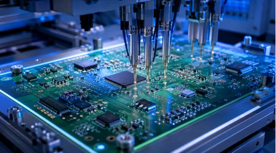
Pre-Production PCBA DFM Check Checklist
Before version freeze, use the PCBA DFM check as a final cross-functional pass. The goal is simple: make open engineering questions visible and owned.
- PCB: stack-up, material, copper, traces, spacing, holes, solder mask, and finish
- Assembly: footprints, polarity, component clearance, BGA/QFN access, and SMT/THT sequence
- DFT: test points, ICT/FCT fixture access, programming, test files, and acceptance criteria
- Data control: Gerber, BOM, placement, drawings, and test documents on the same revision
How to Close DFM Issues Before Production
A useful DFM process ends with decisions, not comments left in an email chain. Each issue should identify the affected location, manufacturing concern, and required action. The team can revise the design, accept a manufacturing recommendation, clarify the specification, or keep the original design by formal confirmation.
Freeze the Approved Revision
After changes, update every related production file. Do not replace the Gerber and forget the BOM or placement data. Once all engineering questions are closed, freeze the approved revision and release that exact file set. Revision control is boring right up until two versions reach the line.
PCBA DFM Check vs First Article Inspection
A PCBA DFM check happens before production release. First Article Inspection happens after the first article is built and checks whether it meets design requirements before larger-volume production continues.
DFM reduces avoidable design and process uncertainty. FAI verifies the actual first build. For a new design or meaningful revision, they work best as complementary controls.
Building a More Production-Ready Review Process
A DFM report becomes more useful when the supplier can connect design feedback with the process that will build and test the board. SCSPCBA supports DFM Analysis, Design Review, PCB Layout Support, Manufacturing Optimization, and Prototype Verification. Its process coverage includes SMT, DIP, BGA/CSP/QFN assembly, double-sided reflow, selective wave soldering, SPI, AOI, X-Ray, ICT, and FCT. MES-based production traceability also connects production and inspection records.
A footprint comment, a hidden-joint inspection plan, and an ICT fixture question all affect the same release. When a project also needs PCB fabrication, sourcing, assembly, testing, and later integration, the one-stop PCBA service provides that broader manufacturing path.
FAQ
Q1: What is a PCBA DFM check?
A: A PCBA DFM check reviews fabrication, assembly, inspection, and test-related design details before production release. Its purpose is to reduce avoidable manufacturing questions and rework risk.
Q2: What is included in a PCB assembly DFM checklist?
A: A PCB assembly DFM checklist typically covers board data, holes, solder mask, footprints, polarity, component clearance, BGA/QFN packages, SMT/THT sequence, test points, ICT/FCT access, and revision control.
Q3: What does design for manufacturing PCBA mean?
A: Design for manufacturing PCBA means checking whether PCB and assembly data fit the intended fabrication, placement, soldering, inspection, and testing processes before production starts.
Q4: Is a PCBA DFM check the same as DRC?
A: No. DRC checks layout rules and constraints. DFM reviews whether the design can move through real manufacturing and assembly processes with the agreed project requirements.
Q5: Does a PCBA DFM check guarantee defect-free production?
A: No. DFM can reduce foreseeable manufacturing, assembly, and test risks, but it cannot remove every possible defect. Prototype verification, First Article Inspection, in-process controls, and final testing still have separate roles.






Leave a Reply
Want to join the discussion?Feel free to contribute!