How Reflow Soldering Affects PCBA Quality
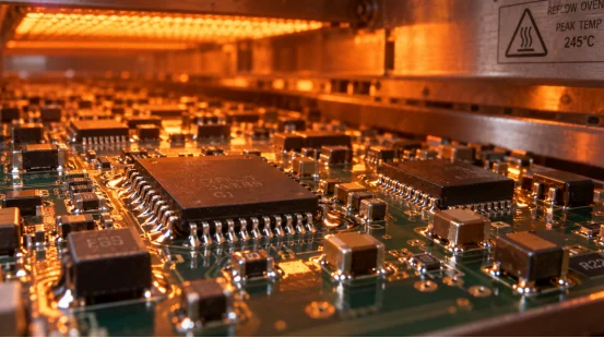
Reflow soldering transforms printed solder paste into structural joints. These joints attach surface-mount components directly to a PCB. The applied heating cycle dictates how this paste melts.
It also determines how the material wets every pad before cooling into a rigid connection. This cycle directly impacts electrical continuity and mechanical strength. Furthermore, it influences thermal life and board repair rates.
Ultimately, the core question remains straightforward. Will the assembly operate flawlessly post-shipment? It must survive constant vibration, intense heat, and routine power cycles.
What Does Reflow Soldering Do to a PCBA?
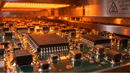
The reflow soldering procedure connects paste printing, component placement, heating, cooling, and inspection. Every phase leaves traceable marks on the finished PCBA. Therefore, quality teams closely examine the full process record alongside actual solder joint outcomes.
How Does the Thermal Profile Shape Solder Joints?
A regulated thermal profile guides the board through specific zones. These include preheat, soak, reflow, and cooling stages. Preheat triggers the flux. Meanwhile, it prevents abrupt thermal expansion. The soak phase pushes the board and components toward a uniform temperature.
Next, the reflow zone elevates the alloy past its liquidus point. It stays there long enough to ensure proper wetting. Finally, cooling firmly locks in the grain structure and joint shape.
Metrics like peak temperature, time above liquidus, ramp rate, and cooling speed are vital. They must perfectly align with the solder alloy, PCB materials, component package, and board mass.
An excessively hot profile introduces severe risks. It might destroy components, detach pads, or worsen board warpage. Conversely, a cool setup causes poor wetting. This creates open, faulty connections. Profile records supply a dependable baseline for every product revision.
Why Do Board Materials and Component Mix Matter?
Large copper areas pull heat away from small pads. Heavy-copper, aluminum, ceramic, rigid-flex, and high-layer-count boards therefore need profile work that reflects their real thermal mass. Mixed packages add another variable. A 0201 resistor, a QFN, and a large connector can reach soldering temperature at different speeds.
The assembly drawing, component datasheets, moisture controls, and PCB finish belong in the same review. DFM and DFT checks can flag pad spacing, thermal relief, stencil apertures, and test-point access before the first article reaches the oven.
Which Reflow Soldering Defects Reduce PCBA Quality?
Defects show how heat, paste, placement, and design interact. The same visible symptom can have several causes, so you need process data and inspection results before selecting a correction.
What Causes Solder Bridging and Solder Balls?
Solder bridging joins neighboring pads and can create a short circuit. Common process contributors include excessive paste volume, stencil aperture design, component misalignment, and a profile that gives the paste poor release or wetting behavior. Solder balls can come from paste spatter, moisture, rapid heating, or contaminated surfaces.
3D solder paste inspection measures paste height, volume, and offset before placement. That early check helps separate printing errors from oven-related causes. AOI after reflow then checks bridging, solder balls, polarity, missing parts, and component offset.
How Do Insufficient Solder and Cold Joints Appear?
Insufficient solder leaves a small or incomplete fillet and reduces the contact area. A cold solder joint has a dull, rough appearance and weak metallurgical bonding. Both conditions can create intermittent faults that appear during vibration or temperature cycling.
Paste age, storage temperature, stencil condition, pad oxidation, and conveyor speed all affect wetting. A documented paste-handling procedure, verified PCB and component incoming inspection, and a stable thermal profile give you direct control points. IPC-A-610 acceptance criteria provide the visual reference for finished assemblies.
Why Are Voids and Head-in-Pillow Concerns for BGA and QFN?
Voids are gas pockets inside a solder joint. A high void ratio reduces the effective metal area and can raise thermal resistance in power or ground connections. Head-in-pillow occurs when a BGA ball and the printed paste separate during heating, leaving an electrical connection that looks formed but has limited bonding.
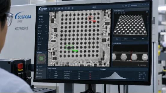
AOI cannot see every hidden joint. X-ray inspection checks BGA, CSP, and QFN areas for void ratio, bridging, and ball integrity. Profile control, pad design, paste selection, and controlled storage work together to reduce these risks.
How Can You Control Reflow Soldering Quality?
Stable quality comes from linked controls across the line. The goal is a traceable chain from incoming materials to solder paste printing, placement, reflow, inspection, electrical testing, and shipment.
Which Inspections Should Follow Reflow?
Use SPI before soldering to measure paste volume, thickness, and offset. Use AOI after placement and reflow for visible defects. Use X-ray for hidden joints. ICT checks circuit connections and component values, while FCT verifies product functions under defined operating conditions. Aging, temperature and humidity, vibration, and salt-spray tests add evidence for products with long service requirements.
FAI confirms the first article before mass production. IPQC samples key processes during the run. OQA confirms appearance and function before shipment. Repaired boards receive a second inspection, closing the loop from discovery to verification.
How Does MES Traceability Help With Reflow Issues?
MES can bind a product serial number to materials, machine data, inspection results, and repair history. When an abnormal solder joint appears, you can locate the affected batch, review its profile and paste records, and contain the right scope. This shortens failure analysis and gives engineering a clear path for corrective action.
How Does SCSPCBA Support Reflow-Centered PCBA Quality?
Reflow control works best when engineering, production, and testing share the same data. SCSPCBA combines SMT assembly with 3D SPI, high-precision reflow ovens, AOI, X-ray, ICT, FCT, and environmental reliability testing. Its process uses IQC, FAI, IPQC, and OQA, with MES records linking materials to shipment.
For automotive programs, IATF 16949 practices support process discipline; IPC-A-610 supports assembly acceptance. The team also handles BGA, CSP, QFN, 0201, and 01005 packages, plus prototype, low-volume, and mass-production builds. That combination lets you review a thermal profile alongside paste data, inspection images, and test results during NPI and production ramp-up. Technical details and project coordination are available through the SCSPCBA website.
FAQ
Q1: What is the main effect of reflow soldering on PCBA quality?
A: It determines how consistently solder joints wet, bond, and cool, which affects electrical continuity, mechanical strength, and service life.
Q2: How do you verify a reflow thermal profile?
A: Attach thermocouples to representative pads and components, record ramp rate, soak, peak temperature, time above liquidus, and cooling rate, then compare the record with the solder and component requirements.
Q3: Which inspection finds hidden BGA defects?
A: X-ray inspection reveals voids, bridging, and ball integrity inside BGA and other hidden joints.
Q4: Can AOI replace electrical testing after reflow?
A: AOI checks visible assembly conditions; ICT and FCT verify circuit behavior and product functions.
Q5: What should you ask a PCBA supplier about reflow quality?
A: Ask for profile records, SPI and AOI coverage, X-ray access for hidden joints, traceability from materials to shipment, and the FAI, IPQC, and OQA plan.





Leave a Reply
Want to join the discussion?Feel free to contribute!