PCB Assembly from Prototype to Mass Production: Solving Volume Challenges for ODM/OEM

Design for Manufacturability (DFM) is the practice of designing …

PCB Assembly Testing & Inspection: Building Trust Through Measurable Quality Control

PCB Assembly Testing & Inspection: Building Trust Through Measurable Quality Control

PCB Assembly Testing & Inspection: How Quality Is Verified at Every Stage

1. Why PCB Assembly Testing & Inspection Matters

In PCB assembly, most failures are not design errors but process-related defects. According to IPC field data, over 60% of electronic failures originate from soldering defects, component placement errors, or insufficient process control.

(1) Discover Defects in Advance to Avoid Batch Losses

During the PCB manufacturing assembly, small welding errors or misplaced components may lead to functional failure of the entire circuit board. Through first article inspection (FAI), process accuracy can be verified before mass production, preventing a large number of defective circuit board due to design or operational errors, and significantly reducing material and labor waste. Research shows that first-piece inspection can control the defective rate below 1%, greatly improving production economy.

(2) Ensure Electrical Performance and Signal Advantages

Electrical performance testing includes continuity testing, insulation resistance testing, and signal defect analysis at high frequencies, which can identify potential problems such as open circuits, short circuits, and crosstalk. These tests not only verify that the circuit works as designed but also identify performance defects caused by improper wiring, ensuring that the PCB assembly is stable and reliable in actual applications.

(3) Improve PCB Manufacturing Reliability and Meet Strict Requirements in Application Scenarios

For fields with high reliability requirements such as medical care, automobiles, and industrial control, PCBs must withstand environmental reliability conditions such as temperature and humidity cycles, vibration, shock, and salt spray. This type of test simulates long-term use, evaluates the circuit board’s ability to withstand extreme environments, and ensures the service life and safety of the printed circuit board production. It is a key step in passing industry certifications (such as ISO 9001, IPC standards).

(4) Support Automated Production and Quality Traceability

Automated means such as automatic optical inspection (AOI), in-circuit testing (ICT) and functional testing (FCT) can achieve efficient and consistent quality control on SMT and DIP production lines. These tests not only detect accuracy, but also generate data records that can be supplemented and improved, while continuously optimizing the process and improving the overall manufacturing level.

(5) Comply with International Standards and Enhance Market Competitiveness

Complying with international standards such as IPC-A-610, ISO 9001, UL, ROSH  etc. can not only standardize and implement quality and technology, but also help companies establish a complete quality management system. PCB boards that meet standards are more likely to earn customers’ trust and compete more effectively in the global market.

Staff conduct first-piece inspection of circuit boards

2. Industry Standards & Quality Benchmarks

Reliable PCBA testing services must rely on authoritative industry standards and strict quality benchmarks to ensure the safety, reliability and compliance of PCB board throughout the entire life cycle of design, manufacturing, assembly and application.

(1) IPC-A-610: Acceptance Standard for Electronic Components

IPC-A-610 is the most widely used assembly quality acceptance standard in the global electronics manufacturing field. It defines three-level product classification and acceptance criteria from consumer to high-reliability products.

  • ‌Class 1 (General Electronic Products)‌
    Suitable for disposable consumer devices, allowing a certain degree of cosmetic defects.
  • ‌Class 2 (dedicated service electronic products)‌
    Used for communication equipment, industrial control, etc., requiring continuous operation but allowing limited shutdown, emphasizing functional reliability.
  • ‌Class 3 (high-performance electronic products)‌
    Suitable for high-reliability scenarios such as automotive, medical, aerospace, etc., requiring zero defect tolerance. The solder joints must be completely wetted, without voids, and without cracks.

Key inspection items include: solder joint shape, pin coplanarity, virtual soldering/bridging identification, intermetallic compound (IMC) thickness control (1–3μm), etc.

(2) IATF 16949: Automotive Process Control and Traceability

IATF 16949 is a quality management system standard unique to the automotive industry

  • Implement five major tools
    PPAP (Production Part Approval Process), FMEA (Failure Mode Analysis), and SPC (Statistical Process Control)
  • Complete process traceability, basic raw materials, process parameters, inspection records
  • Must pass 1000 thermal cycle tests (-40℃ to 125℃), the gold layer does not fall off, and the contact resistance change is ≤10%

Circuit board manufacturing such as automotive light panels, ECUs, and ADAS systems must meet this standard before they can enter the OEM supply chain.

(3) UL and RoHS: Safety and Material Compliance

  • UL certification (safety standards)
    Verify the insulation performance, temperature resistance level, and flame retardancy of the PCB (for example, FR-4 materials need to pass UL94-V0)
    Commonly used in power modules, home appliance control panels and other fields to ensure that there is no risk of fire or electric shock during use
  • RoHS directive (environmental protection standards)
    Contents of six harmful substances including lead, heart disease, and mercury, applicable to all electronic products entering the EU market
    The corresponding domestic standard is GB/T 26572, and the detection method refers to GB/T 26125 (followed by IEC 62321)

Complying with UL + RoHS at the same time means that the circuit board is both safe and environmentally friendly, improving the competitiveness in the international market.

(4) ISO Series Standards: Quality Management and Extension to Specific Industries

ISO standard application areas core requirements
ISO 9001 General quality management Establish a PDCA cycle to ensure that the process is stable and controllable
ISO 14001 Environmental management Control waste emissions, energy consumption, and use of hazardous substances
ISO 13485 Medical equipment Emphasize biocompatibility, sterile processing, and traceability
ISO 45001 Occupational health and safety Ensure the safety of production personnel

PCBA Testing Industry Standards and Quality

3. In-Process Inspection: SPI, AOI, X-Ray & Traceability

In the SCS PCBA circuit board assembly, the quality control of the SMT and DIP assembly processes is combined with the MES system through detection technologies such as SPI, AOI, and X-Ray to achieve full-process closed-loop control from process foundation to finished product quality.

(1) 3D SPI – Solder Paste Detection

SPI (Solder Paste Inspection) performs 3D measurements of solder paste thickness, volume, and offset after printing and before patching to detect insufficient solder paste, bridging risks, and template problems to ensure a reliable welding foundation.

  • The solder paste thickness is controlled at 0.1–0.15mm, and the deviation does not exceed ±10%.
  • Detect defects such as less tin, more tin, bridging, and pulling points to prevent soldering or short circuits after reflow soldering.
  • The BGA area is required to have a solder paste filling degree of more than 90%.
  • SPI solder paste volume tolerance: ±25%

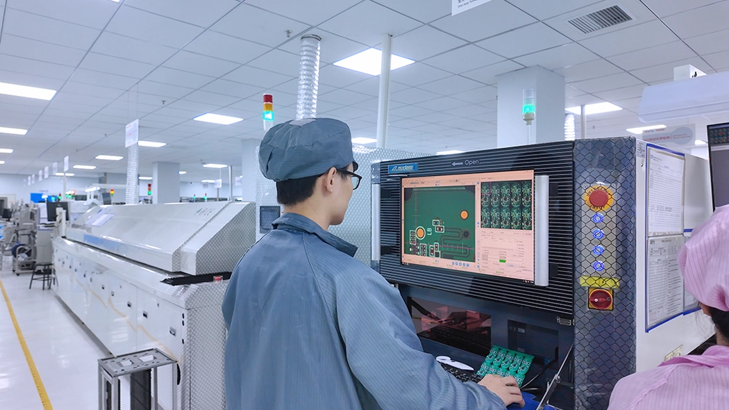
3D SPI equipment shows that the circuit board status is “good”

(2) AOI – Automatic Optical Inspection

AOI (Automatic Optical Inspection) performs inspections after component placement and after reflow soldering, identifying issues such as missing components, misalignment, reversed polarity, solder bridging, and insufficient soldering.

  • After component placement
    Verifies correct component position, angle, and polarity.
  • After reflow soldering
    Analyzes solder joint wetting angle, solder volume, and shape, identifying defects such as cold joints and solder balls.
  • AOI inspection accuracy: ≥99.5%

The staff are using AOI equipment to inspect the circuit boards.

(3)X-Ray Inspection

X-ray inspection is used to detect packaging types that cannot be observed with the naked eye or AOI (Automated Optical Inspection), such as bottom solder joints of BGA, CSP, and QFN packages.

  • It utilizes the penetrating power of X-rays to observe solder ball integrity, void rate, and bridging.
  • It can detect inter-layer connections within PCBs and damage to component packaging.
  • For high-density electronic PCB assembly and manufacturing used in mobile phones and laptops, the reliability requirements for solder joints are extremely high.

X-ray inspection BGA, CSP, and QFN packages

(4) MES System – Full Process Traceability

The MES system integrates inspection data from SPI, AOI, and X-Ray equipment with the production process, building a complete quality data chain.

  • Real-time monitoring
    Collects parameters from equipment such as pick-and-place machines and reflow ovens, enabling visualization of key indicators.
  • Error prevention management
    Scans material tray barcodes during loading, and the system automatically compares them with the BOM to prevent material errors.
  • Full traceability
    Establishes forward and backward traceability from raw material batches → solder paste printing → component placement → testing → repair → packaging.
  • Data closed loop
    Inspection results are automatically linked to product serial numbers, supporting anomaly alerts.

SCSPCBA introduces the MES system into the SMT process, combining it with SPI + AOI + X-Ray triple inspection. A process history file is created for each printed circuit board production, enabling precise defect location and rapid containment.

4. Functional & Reliability Testing – Which Test Fits Which Project?

Not all projects need the same testing depth.

Test Type Best For Risk Coverage
ICT Medium–high volume boards Open/short, component value
FCT Function-critical products Real operating behavior
Burn-In Power & industrial Early failure screening
Environmental Automotive/outdoor Thermal & humidity stress

5. Testing Facilities & Capability at SCSPCBA

(1) Independent Testing Laboratory

SCSPCBA has established a dedicated testing laboratory independent of the PCB board production line to ensure that the testing environment is free from production interference and to achieve comprehensive quality control throughout the entire process. The laboratory adopts a partitioned management model, encompassing functional testing, environmental simulation, fault analysis, and clean repair areas. It is equipped with an intelligent monitoring system that records test data in real time and integrates with the production system.

SCSPCBA has established a dedicated testing laboratory for pcb fabrication and assembly

(2) Core Testing Equipment Configuration

3D SPI System

  • Utilizing laser scanning technology, it achieves precise three-dimensional measurement of solder joints with a detection accuracy of ±0.01mm, capable of identifying minute defects such as cold solder joints and short circuits.
  • Integrated with AI algorithms, it automatically compares the design model with the actual welding results and generates a visual quality report.

High-Resolution AOI Inspection Line

  • Equipped with a 4K industrial camera and multi-spectral imaging technology, it performs full inspection of the circuit board manufacturing surface, identifying defects such as scratches, oxidation, and component misalignment, with a false negative rate of less than 0.01%.
  • Supports automatic storage and classification of NG (Not Good) images, facilitating root cause analysis of defects.

X-ray Inspection Machine

  • Using a microfocus X-ray source and flat panel detector, it achieves non-destructive testing of the internal structure of BGA, CSP, and other packaging forms, with a resolution of 5μm.
  • Integrates automatic defect marking function, accurately locating hidden defects such as voids and cracks.

ICT and FCT Test Stations

  • The ICT (In-Circuit Test) system verifies the electrical performance of circuit board through probe contact testing, supporting mixed-signal testing of analog and digital circuits.
  • The FCT (Functional Test) platform simulates the actual working environment, performing aging tests and functional verification on finished products to ensure product reliability.

Environmental Simulation Equipment

  • Vibration Testing Machine
    Simulates mechanical stress during transportation and use, with a test frequency range of 0-5kHz and acceleration up to 10g.
  • Temperature and Humidity Test Chamber
    Covers a temperature range of -40℃ to +125℃, with humidity control accuracy of ±2%, used for accelerated aging testing.
  • Salt Spray Test Chamber
    Complies with GB/T 2423.17 standard, simulating corrosion in coastal environments, with adjustable test cycles.

Salt spray test chamber specifically designed for circuit board testing.

Fault Analysis and Repair Facilities

  • Equipped with Class 100 clean workstations and anti-static equipment, supporting tools such as microscopes and X-ray flaw detectors for defect localization and repair.
  • The repair process is controlled by SOP (Standard Operating Procedures) to ensure that repaired printed circuit board assembly services meet the original design requirements.

(3) Quality Control System

Layered Inspection Mechanism

  • First Article Inspection (FAI)
    A full-item inspection of the first produced unit is conducted before mass PCB board production begins to confirm that process parameters are consistent with design requirements.
  • In-Process Quality Control (IPQC)
    Sampling inspections are conducted after key processes such as SMT placement and wave soldering to intercept defects in real time.
  • Outgoing Quality Assurance (OQA)
    100% functional testing and visual inspection are performed before finished products are shipped to ensure zero-defect delivery.

Defect Closed-Loop Management

  • Real-time defect data is collected through the MES (Manufacturing Execution System), automatically triggering alerts and sending them to the relevant personnel.
  • A defect database is established to analyze high-frequency problems and to drive optimization of the printed circuit board manufacturing process and adjustments to equipment parameters.
  • PCB circuit board requiring rework must undergo secondary testing to ensure that the problems are completely resolved, forming a closed loop of “discovery-analysis-improvement-verification.”

The staff are currently performing Outgoing Quality Assurance (OQA) on the finished circuit boards.

6. SCSPCBA PCB Assembly and Testing: The Complete Process

PCB assembly and testing are not single processes but rather a multi-level quality control system that spans the entire process from raw material warehousing to finished product shipment. The following is SCSPCBA’s core testing process:

(1) PCB Raw Material Incoming Inspection

  • PCB Substrate
    Inspect for surface contamination, scratches, deformation, hole position accuracy, and impedance matching.
  • PCB Board Components
    Verify model number, polarity, and package dimensions; check for compliance with moisture sensitivity level (MSL).
  • Solder Paste and Flux
    Verify viscosity, metal content, activity, and storage conditions.

Common tools: Optical microscope, automatic optical inspection (AOI) system, hygrometer

(2) PCB Manufacturing Process monitoring

Manufacturing Process Inspection Items
Solder paste printing Printing thickness, misalignment, leakage, blurring
SMT Assembly Component presence/absence, positional deviation, polarity reversal, and lifting/tilting
Reflow soldering Temperature profile monitoring, wettability, bridging, cold solder joints
Wave soldering Solder joint fullness, solder penetration rate, shadowing effect

Real-time monitoring can effectively intercept over 90% of early-stage defects.

(3) Post-Assembly Testing

  • Visual Inspection
    Using AOI (Automated Optical Inspection) to check solder joint quality, missing or misplaced components.
  • Electrical Performance Testing
    • In-Circuit Test (ICT): Using a test fixture to detect open circuits and short circuits.
    • Flying Probe Test: Suitable for small batches and high-density boards.
  •  Functional Test (FCT)
    Simulating the actual working environment to verify overall system performance.
  • X-ray Inspection
    Used for quality assessment of hidden solder joints such as BGA and QFN.

(4) Reliability Verification Testing

  • Temperature and humidity cycling test (-40℃~+85℃)
  • Vibration and shock testing
  • Salt spray test (applicable to outdoor equipment)
  • High-temperature aging test (Burn-in)

(5) OQA Inspection and Final Approval

(6) Packaging and Shipment Traceability

These tests ensure the long-term stable operation of the PCB board assembly in complex environments and form the basis for certifications such as ISO 9001 and IATF 16949.

PCB/PCBA testing and inspection services

pcb printed circuit board assembly testing

7. How to choose the right PCB/PCBA testing method?

(1) PCB Manufacturing (Bare Board Stage)

  • Open/Short Circuit Test
    Using flying probes or test fixtures, verify the continuity and insulation of the traces to ensure there are no open or short circuits. Applicable to all PCBs, this is a fundamental and mandatory test.
  • Impedance Test
    For high-speed signal lines (such as USB and HDMI), measure the characteristic impedance using a TDR to ensure it meets design tolerances (typically ±10%).
  • High Voltage Withstand Test (Hi-Pot)
    Apply 500V DC for 30 seconds to high-voltage boards (such as power modules) to test interlayer insulation performance.

(2) Post-Assembly (PCBA Stage)

  • AOI (Automated Optical Inspection)
    Uses multi-angle cameras to scan solder joints and component positions, identifying surface defects such as missing components, misaligned components, misalignment, and bridging. Suitable for mass production, but cannot inspect BGA bottom solder joints.
  • ICT (In-Circuit Testing)
    Uses a bed of probes to contact test points, measuring resistance, capacitance, and polarity to locate component-level faults. High accuracy and coverage exceeding 95%, but requires custom fixtures; suitable for large-volume orders.
  • Flying Probe Testing
    Moves probes to sequentially contact test points, requiring no fixtures; suitable for prototyping or small-batch production. Disadvantages include slow speed and unsuitability for high-density boards.
  • Automated X-ray Inspection
    Specifically designed for hidden packages such as BGA and QFN, detecting solder voids, cold solder joints, and internal short circuits. A critical step in automotive electronics and medical equipment.

(3) Functional and Reliability Verification

  • FCT (Functional Testing)
    Simulates actual working conditions to verify the overall board functionality (e.g., communication interfaces, software operation).
  • Environmental Stress Testing
    • Temperature Cycling
      Cycling from -40℃ to 125℃ to examine the risk of fracture due to thermal expansion and contraction.
    • Vibration Testing
      1 hour each along the X/Y/Z axes to assess vibration resistance.
    • High Temperature and High Humidity Testing
      Running for several days in an 85°C/85%RH environment to accelerate aging and assess lifespan.
  • Burn-in Testing
    Running for 48-72 hours with power on to prematurely expose components prone to “early failure,” improving the reliability of circuit board manufacturing leaving the factory.

(4)  Test Items in Different Application Fields

Application areas core standards Test items
Automotive electronics IATF 16949 + IPC-A-610 Class 3 Thermal cycling, vibration, salt spray, PPAP files
Medical equipment ISO 13485 + ISO 10993 + IPC-A-610 Ionic contamination, chemical resistance, and biocompatibility
Industrial control IPC-A-610 Class 2 + ISO 9001 Continuity test, insulation resistance, high temperature aging
Aerospace MIL-P-45204 + IPC-A-610 Class 3 Gold layer thickness ≥0.76μm, no corrosion in salt spray for 96 hours
Outdoor communications IEC 60068-2-30 + ISO 9227 Temperature and humidity cycle, UV aging, salt spray test
  • Mass Printed Circuit Board Production
    Prioritize ICT+FCT. Although initial investment is high, the unit cost is low and efficiency is high.
  • Prototyping or R&D Stage
    Use flying probes instead of ICT to save on fixture manufacturing time and costs.

Get a BOM Quote with Testing Plan Recommendation

Talk to an Engineer About Your PCBA Testing Strategy

How-to-Compare-PCBA-Quotes-cost-baskets
From Prototype to Mass Production: Consumer Electronics PCB Assembly

From Prototype to Mass Production: Consumer Electronics PCB Assembly

Design for Manufacturability (DFM) is the practice of designing …
Industrial Control PCBA Solutions With Strict DFM and MES Control

Industrial Control PCBA Solutions With Strict DFM and MES Control

Industrial Control PCB Assembly: Reliable PCBA Solutions for Industrial Control

1. Industrial Control PCBA: The Core of Reliable Automation Systems

Industrial control printed circuit board assembly carries and implements crucial functions such as signal sensing, data processing, logical decision-making, and instruction execution in industrial automation systems. Specifically, this is reflected in the following aspects:

(1) As the Physical Carrier of The Control System

Industrial control PCBA is the hardware foundation of core control equipment such as PLCs (Programmable Logic Controllers), DCS (Distributed Control Systems), servo drives, and human-machine interfaces (HMI). It provides a physical mounting platform and electrical connection pathways for all electronic components, including microprocessors (MCU/MPU), memory, sensor interfaces, communication chips, and power modules.

(2) Automation Systems Rely on Real-time Data Flow

The circuits on the PCBA receive weak analog signals from sensors such as temperature, pressure, and position, and preprocess them through amplification, filtering, and isolation (such as using optocouplers) to eliminate electromagnetic interference in the industrial environment.

(3) Ensuring System Reliability and Stability in Harsh Environments

Industrial control PCBAs must be designed and manufactured using more durable materials and stricter process standards to withstand harsh industrial environments such as high and low temperatures, humidity, dust, vibration, and strong electromagnetic interference.

2. Industrial Control PCBA Application Scenarios

Industrial control PCBA is widely used in:

(1) Programmable Logic Controllers (PLCs)

PLCs are the brains of industrial automation, and their core is highly reliable PCB assembly and manufacturing. These circuit boards are responsible for receiving signals from sensors, executing preset logic programs, and outputting control commands to actuators such as motors and valves, thereby achieving automated control of production lines and machinery.

(2) Industrial Sensors and Measuring Instruments

Whether monitoring temperature, pressure, flow rate, liquid level, or other physical parameters, industrial sensors and measuring instruments rely on precise PCB fabrication and assembly to collect weak analog signals, amplify them, and perform analog-to-digital conversion, then output or transmit the processed data. These PCB manufacturing assemblies require high precision and resistance to industrial environmental interference.

(3) Industrial Robots

The joint drives, motion control, and sensing systems of industrial robots all rely on assembly boards. They are used to process data from encoders, torque sensors, etc., run complex motion control algorithms, and drive servo motors to achieve precise and coordinated movements.

(4) Motor Drives and Control

In various industrial equipment, from large pumps to precision machine tools, PCBAs are used to build motor drivers and controllers, enabling precise control of motor speed, torque, and position.

(5) Industrial Communication and Network Interfaces

PCBA manufacturing is used to manufacture communication devices such as industrial Ethernet switches and fieldbus gateways (e.g., Profibus, Modbus), ensuring stable and real-time transmission of control signals and data in the factory network.

(6) Human-Machine Interfaces (HMIs) and Control Panels

The touch screens, control panels, and operator consoles used by factory operators all contain circuit board assemblies, which are used to process user input, display operating status and alarm information, and communicate with the higher-level control system.

3. Stability and Anti-Interference: Core Requirements of Industrial PCBA

Industrial control boards face strong electromagnetic interference (EMI) and unstable power environments. Key requirements include:

  • Multi-layer PCB with optimized grounding and power planes
  • Strict impedance control and signal integrity design
  • EMI/ESD protection layout and component placement
  • High-temperature, long-life industrial-grade components

A single unstable solder joint or layout flaw can cause system downtime, making high-reliability industrial printed circuit board assembly manufacturing essential.

high-reliability SMT lines for industrial control printed circuit board manufacturing

4.  Industrial-Grade PCBA Manufacturing Configuration at SCSPCBA

(1) High-Reliability SMT Lines for Industrial Control PCBA Manufacturing

SCSPCBA operates 5 SMT production lines, specifically configured to support industrial control PCBA, automotive electronics, and medical electronics—not just consumer products.

☆ High-End Multi-Function SMT Line (2+1 Configuration) – 1 Line

  • This line is dedicated to high-reliability applications, including:
    • Industrial control PCBA
    • Automotive electronics
    • Medical electronics
    • Communication equipment
  • Key advantages for industrial PCB assembly:
    • Supports high-mix, high-density, multi-layer PCB
    • Suitable for fine-pitch BGA, QFN, and complex IC packages
    • Stable process control for long-life industrial products
    • Ideal for anti-interference and high-consistency automation PCB assembly

This SMT line is where industrial-grade PCBA requirements are truly met, rather than adapted from consumer production.

☆ Standard SMT Lines (1+1 Configuration) – 3 Lines

Primarily used for consumer electronics, these lines are strictly isolated from industrial control projects.

Industrial control PCBA is not mixed with high-speed consumer orders, ensuring:

  • Stable process parameters
  • Reduced changeover risk
  • Better quality consistency

☆ Dedicated Sample SMT Line – 1 Line

Designed for:

  • Industrial control PCBA prototypes
  • Engineering samples
  • Small-batch trial production

This allows OEM & ODM customers to move smoothly from prototype → pilot → mass production without changing manufacturing logic.

☆ SMT Production Capacity

  • 40,000,000/point/day

High capacity ensures:

Stable delivery for long-term industrial PCBA projects

Scalability for automation customers entering mass circuit board manufacturing production

(2) Industrial-Focused DIP Assembly Capability

Industrial control boards often include power components, connectors, relays, transformers, which require reliable through-hole assembly.

SCSPCBA provides 2 DIP production lines, optimized for industrial reliability.

☆ Selective Soldering Line – 1 Line

Dedicated to small-batch, high-reliability orders, including:

  • Industrial control PCBA
  • Automotive electronics
  • Medical electronics

Advantages for industrial PCBA:

  • Precise soldering for mixed SMT + DIP boards
  • Reduced thermal stress on sensitive components
  • Higher solder joint consistency than wave soldering

This is especially important for PLC boards, control modules, and power control PCB board production.

☆ Wave Soldering Lines – 2 Lines

Mainly used for:

  • Consumer electronics
  • Large-volume standardized products

Industrial projects are selectively assigned, avoiding unnecessary printed circuit board manufacturing process risk.

☆ Manual Soldering Lines – 2 Lines (8 Skilled Operators)

Used for:

  • Industrial samples
  • Small-batch control boards
  • Customized or non-standard components

Manual soldering is controlled, documented, and inspected—not used as a shortcut, but as a precision supplement for industrial control PCBA.

☆ DIP Production Capacity

  • 350,000 solder joints per day

Ensures reliability without sacrificing delivery time.

DIP production line specifically designed for small-batch, high-reliability industrial control PCBA

(3) Assembly & Testing Lines for Industrial Control Systems

SCSPCBA operates 2 dedicated assembly & testing lines, essential for industrial control products that require functional validation, not just visual inspection.

☆ Testing Capability

6 functional test stations supports:

  • Power-on testing
  • Signal verification
  • Load simulation
  • Custom test fixtures

Functional testing is critical for industrial PCB assembly, where field failure is unacceptable.

☆ Final Assembly Capability

20 assembly workstations supports:

  • Control box assembly
  • Cable & connector integration
  • Industrial enclosure assembly

This enables PCBA + box build services for automation and industrial control systems.

(4) Manufacturing Efficiency Reflects Industrial Maturity

SCSPCBA’s manufacturing data demonstrates process maturity, not labor dependency.

  • Annual production value: 1.6 million (pure PCBA processing)
  • Per capita production value: 20,000

This indicates:

  • High automation level
  • Stable process control
  • Lower human error rate

For industrial control PCBA, process stability is more important than sheer labor scale

5. DFM Advantage: Reducing Risk Before Production

At SCSPCBA, DFM is implemented as a manufacturing-driven design optimization system, ensuring that potential risks are identified and eliminated before mass pcb assembly production begins.

SCSPCBA DFM System for Industrial Control PCBA

SCSPCBA provides a structured DFM analysis workflow, specifically tailored for industrial PCB assembly and automation PCBA, covering the following critical dimensions

(1) PCB Stack-Up & Material Optimization

Industrial control PCBA often operates in environments with electrical noise, thermal stress, and long duty cycles.

SCSPCBA evaluates:

  • PCB layer stack-up structure
  • Copper thickness and dielectric material selection
  • Signal, power, and ground plane distribution
  • Impedance consistency and EMC considerations

Improved signal integrity, reduced EMI risk, and enhanced long-term stability for industrial control PCB assembly.

(2) Pad Design & Soldering Reliability Checks

Solder joint reliability is a crucial factor in automation PCB assembly, particularly for applications that are prone to vibration and require high current.

DFM checks include:

  • Pad size, shape, and symmetry verification
  • Fine-pitch BGA / QFN solder joint reliability analysis
  • Mixed SMT + THT process compatibility
  • Solder fillet quality and thermal balance assessment

Lower risk of cold solder joints, tombstoning, voiding, and long-term fatigue failure.

(3) Thermal Design & Heat Dissipation Optimization

Thermal issues are one of the most common root causes of industrial electronics failure.

SCSPCBA’s DFM system analyzes:

  • High-power component placement
  • Copper pour and thermal via design
  • Heat flow paths across PCB layers

Compatibility with enclosure-level heat dissipation

(4)  BOM Risk Analysis & Component Strategy

Industrial projects often require long lifecycle support and supply chain stability.

SCSPCBA performs:

  • BOM completeness and consistency checks
  • Lifecycle and EOL (End-of-Life) risk assessment
  • Alternative component validation
  • Cost-performance optimization without reliability compromise

Reduced supply chain disruption risk and improved cost control for industrial PCB fabrication and assembly projects.

(5) Why DFM Matters for Industrial Control PCB Assembly

Unlike factories that address issues during production, SCSPCBA applies a DFM-first approach, where:

  • Engineering feedback precedes tooling and SMT programming
  • Design risks are corrected before volume scaling
  • Manufacturing feasibility is validated upfront

This approach significantly reduces:

  • Production rework
  • Yield loss
  • Field failure and after-sales risk

DFM ensures the smooth implementation of mass production for industrial control PCBA

6. MES System: Full Traceability for Industrial Control PCBA

SCSPCBA’s MES system enables:

Component batch-level traceability

Real-time production data monitoring

Process parameter recording for each PCB fabrication process

Quality history tracking for audits and after-sales support

This is especially critical for OEM and ODM industrial PCBA projects

MES system management in industrial control PCBA

7. Industrial Control PCBA Online Quotation

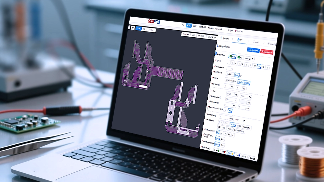
(1) How the Industrial PCBA Online Quotation System Works

To start an industrial PCB assembly quotation, customers simply upload:

  • PCB File – for PCB structure, layer stack-up, and process evaluation
  • BOM list – for component sourcing, lifecycle assessment, and cost analysis
  • Assembly File – assembly soldering, surface mount pcb assembly, soldering assembly, reflow soldering

Based on these file and list, the system generates a fast and transparent preliminary quotation covering:

  • PCB board fabrication
  • SMT assembly
  • Through-hole (DIP / selective soldering)
  • Functional testing
  • Optional box build and final assembly services

This enables OEM and ODM customers to quickly evaluate project feasibility and budget.

(2) Why Online Quotation Is Reliable for Industrial Control PCBA

SCSPCBA’s quotation system is built on actual industrial manufacturing data, including:

  • SMT and DIP line capabilities
  • Process time and testing workload
  • Quality control and traceability requirements
  • Engineering support and DFM involvement

As a result, customers receive:

  • Realistic pricing
  • Predictable lead time
  • Fewer changes during production

This is critical for industrial PCB assembly and automation PCB projects, where late-stage changes create high risk and cost.

(3) Supporting OEM & ODM Industrial Control PCBA Projects

The PCBA online quotation system is particularly valuable for:

  • OEM customers evaluating new industrial control products
  • ODM customers comparing manufacturing strategies
  • Automation companies scaling from prototype to mass production

Combined with SCSPCBA’s DFM and MES systems, the quotation process becomes part of a controlled and traceable manufacturing workflow.

If you are planning an industrial control PCBA or automation PCB assembly project, SCSPCBA’s online quotation system provides a fast, transparent, and engineering-backed starting point.

Get Your Industrial Control PCBA Quotation Today

8. How OEM & ODM Customers Choose Industrial Control Printed Circuit Manufacturing

For OEM and ODM clients, the right partner should offer:

  • Proven industrial PCBA experience
  • Strong DFM and engineering support
  • Stable supply chain and MES system
  • Scalable production capacity

SCSPCBA supports OEM and ODM industrial control PCBA from prototype to mass production, helping customers shorten time-to-market while maintaining quality.

9. Industrial Control PCBA Case Sharing: From Online Quotation to Stable Mass Production

An industrial automation manufacturer (OEM) uses products for factory control systems that operate in high-interference and high-load environments for a long time and have extremely high requirements for stability, maintainability and consistency of equipment.

(1) Customers Use SCSPCBA Industrial PCBA Online Quotation System

The customer uploaded the following files through SCSPCBA’s Industrial Control PCBA Online Quotation System:

  • PCB File(Gerber)
  • BOM List
  • Assembly File

The system quickly generated a preliminary quotation for Industrial PCB Assembly, covering:

  • PCB manufacturing
  • SMT placement
  • THT / DIP process
  • Function test

(2) Use DFM Analysis System

Before confirming manufacturing of the industrial control PCBA board, the SCSPCBA engineering team initiated a DFM (Design for Manufacturability) analysis based on the customer documentation.

DFM focuses on discovering and optimizing the following issues:

  • PCB stack-up and grounding structure:
    Optimize power and ground plane layout to reduce EMI risks in industrial environments
  • Key device pad design:
    Adjust the pads of some high-power and interface devices to improve welding reliability
  • Thermal design issues:
    Optimize copper foil laying and heat dissipation paths for control boards that continue to work

(3) The MES System Ensures Traceability of Industrial Control PCBA Manufacturing

PCBA enters the later stage of production, and SCPCBA’s MES monitors the entire process.

The MES system implemented in this industrial control PCBA project:

  • Missing batch level supplement
  • SMT/DIP Problem Parameter Logging
  • Test data binding for each PCBA
  • Production exceptions can be traced back and quickly positioned

(4) Industrial Control Grade PCBA Project Results

One-off small batch production
The functional test pass rate is significantly higher than the customer’s previous projects
No on-site abnormalities caused by manufacturing issues
Smoothly enter the subsequent mass production stage

Customer feedback:

“SCPCBA’s online quotation is not a simple price calculation, but takes engineering, manufacturing and risk control into consideration, which is very critical for industrial control PCBA.”

If you are developing or upgrading industrial control PCBA/automated PCB assembly projects:

Upload your PCB file + BOM list + assembly file

Suitable for PCB assembly manufacturing used in various industries, including industrial control.


9. Industrial control PCBA FAQ

Industrial PCB assembly focuses on stability, anti-interference, long lifecycle components, and strict process control, while consumer PCBA prioritizes cost and speed.

Industrial control PCBA is widely used in:

  • Factory automation
  • Robotics and motion control
  • Energy and power systems
  • Industrial communication equipment
  • Smart manufacturing and MES-connected devices

Key requirements include:

  • Strong EMI/ESD resistance
  • Stable power and signal integrity
  • High solder joint reliability
  • Continuous operation under harsh environments

Common types include:

  • Multi-layer control boards
  • Power control PCBA
  • PLC main boards
  • Signal acquisition and processing boards
  • Industrial communication boards

SCSPCBA’s DFM system includes:

  • PCB stack-up and material evaluation
  • Pad design and soldering reliability checks
  • Thermal design optimization
  • BOM risk analysis and alternative component suggestions

Yes. SCSPCBA supports prototypes, pilot runs, and scalable mass production, allowing OEM and ODM customers to grow without changing suppliers.

Typical testing includes:

  • AOI and X-Ray inspection
  • ICT testing
  • Functional testing under load
  • Customized test fixtures for control systems

Yes. SCSPCBA offers an industrial PCBA online quote system for fast and transparent pricing based on Gerber files, BOM, and assembly data.

Absolutely. SCSPCBA supports both OEM and ODM industrial PCBA, offering DFM support, supply chain management, testing, and optional box build services.

Yes. All industrial quotations are reviewed by engineers after system pricing, ensuring manufacturability, reliability, and realistic lead times.

How-to-Compare-PCBA-Quotes-cost-baskets
ISO-Compliant Medical Electronics PCBA Ensures Safety, Traceability, and Long-Term Reliability

How ISO-Compliant Medical Electronics PCBA Ensures Safety, Traceability, and Long-Term Reliability

Design for Manufacturability (DFM) is the practice of designing …
Vietnam PCBA Factory Supports OEM & ODM Manufacturing for Global Markets

How a Vietnam PCBA Factory Supports OEM & ODM Manufacturing for Global Markets

Design for Manufacturability (DFM) is the practice of designing …

SCSPCBA PCBA MES System

SCSPCBA MES System: A Unified Manufacturing Execution Platform for PCB & PCBA

Design for Manufacturability (DFM) is the practice of designing …

Best Wishes for the New Year 2026

Best Wishes for the New Year 2026: Manufacturing Support Continues Without Interruption

Continuous PCB, PCBA, and Box Build Services

Celebrating the New Year While Keeping Manufacturing Moving

As the New Year begins, SCSPCBA would like to extend our sincere wishes for a happy, healthy, and successful year ahead to all our customers and partners worldwide. While this season is traditionally a time for celebration and rest, manufacturing timelines and project schedules do not always pause.

To ensure uninterrupted support for OEM and ODM customers, SCSPCBA continues normal operations throughout the New Year holiday period, maintaining stable manufacturing execution and responsive engineering support.

PCB, PCBA, and Box Build Quoting Platform Remains Fully Operational

During the New Year holiday, SCSPCBA’s online PCB, PCBA, and Box Build assembly quoting platform remains fully functional and accessible 24/7.

Customers can continue to:

  • Upload Gerber files and BOMs
  • Receive automated PCB and PCBA cost estimates
  • Configure box build assembly requirements
  • Review lead time and manufacturing options

The platform integrates PCB fabrication, SMT assembly, PCBA testing, and box build assembly pricing into a single workflow, allowing customers to plan projects efficiently—even during holiday periods.

Customer Support Always Online

As we move into the New Year, SCSPCBA remains focused on delivering transparent pricing, stable execution, and high-quality PCB, PCBA, and box build assembly services.

Whether you need technical support, assistance with material sourcing, or order progress updates, our support channels will remain open and responsive.

  • Email: sales@scspcba.com
  • Website: https://www.scspcba.com

If you are planning new projects, feel free to use our online quoting platform or contact our team at any time.

How-to-Compare-PCBA-Quotes-cost-baskets
Box Build Quote Service

Box Build Quote Service: A Practical One-Stop PCBA Solution for OEM & ODM

Design for Manufacturability (DFM) is the practice of designing …