Flying Probe vs. ICT: How to Choose Electrical Testing for PCBA Prototypes
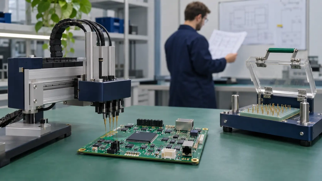
For a PCBA prototype, choose electrical testing around the questions the build must answer, the available probe access and the stability of the design. Flying probe testing uses movable probes; conventional fixture-based in-circuit testing uses a fixed contact arrangement. A prototype may suit flying probe testing, while a stable production design may justify a dedicated ICT fixture. Neither choice establishes the complete test plan by itself.
For an AI hardware project, start with the actual board and its intended verification. An edge-computing module and a larger computing assembly should not receive an identical test specification simply because both carry an AI application label.
Start with the electrical questions
Write down what the engineering team wants to establish before discussing equipment. Does the build need board-level interconnection checks, component-parameter measurements, verification of powered functions, or a combination? Separate those questions so the supplier can propose a suitable approach.
ICT mainly checks board-level interconnections and component parameters. Functional circuit testing, or FCT, verifies whether the assembled board performs its designed functions under the selected operating conditions. Discussing PCBA testing and inspection at this level makes the inquiry more specific than asking whether a factory has a particular machine.
State that the request concerns an assembled PCBA. Keep bare-board electrical verification and assembled-board checks as separate items in the quotation. Specify which manufacturing stage each requested result belongs to, rather than relying on the phrase “PCB electrical test” to communicate the whole scope.
Understand how the probes reach the board
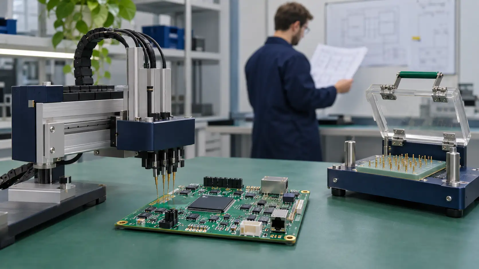
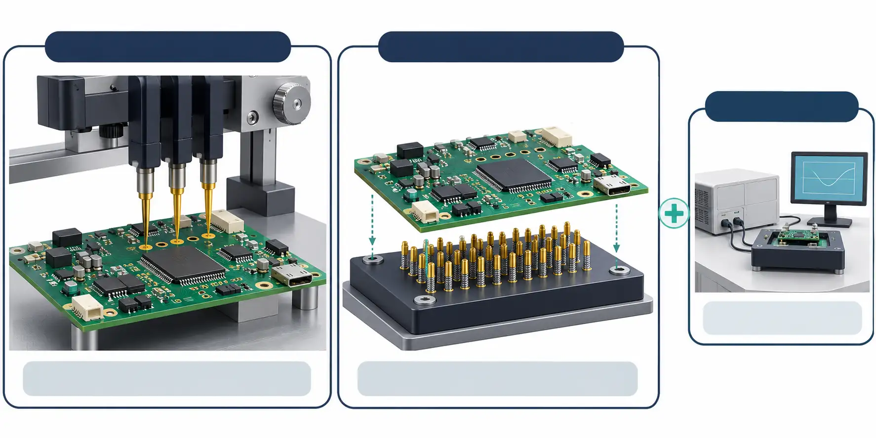
A flying probe tester moves its probes to make contact with selected points. A conventional bed-of-nails arrangement uses a fixed set of contacts aligned with the board’s test points. That difference makes probe access and fixture commitment central to the comparison.
Design for testability includes test coverage, unobstructed access and compatibility with the proposed equipment. Test points are pads reserved for probe contact during ICT or flying probe testing. Moving probes do not remove the need to review where the equipment can make suitable contact.
Provide the current layout and assembly information for an access review. Request feedback on inaccessible locations, obstructions and the proposed contact side. Where a connection cannot be measured as intended, record the limitation and discuss another verification approach. Do this before treating a quoted method as agreed coverage.
During layout review, test-point access and assembly constraints belong in the same engineering conversation. Keep the resulting decisions tied to the file revision that the test engineer actually reviewed.
Compare fixture investment against design stability
During prototype or small-volume production, flying probe testing can be combined with AOI and FCT to reduce investment in dedicated fixtures. For mass-production PCBAs, ICT, AOI and FCT may be configured around coverage and cost. These are starting points for project planning, rather than a universal quantity threshold.
Request separate quotations for test preparation and execution where practical. Identify which work belongs to programming, a dedicated fixture, validation, maintenance and testing the batch. Ask what happens to those items if the layout or component population changes before the next build.
An early design with unresolved test-point positions deserves a different purchasing discussion from a released board expected to repeat. Describe the planned revisions and production scenarios to the supplier. Compare the proposals against those scenarios instead of assuming the smallest initial tooling charge produces the lowest overall testing cost.
| Decision area | Flying probe discussion | Fixture-based ICT discussion |
| Probe access | Which locations can movable probes reach? | Which test points will the fixture contact? |
| Design changes | What program or access review follows a revision? | What fixture or program changes follow a revision? |
| Investment | What preparation and batch-testing work is quoted? | What tooling, validation and maintenance are quoted? |
| Coverage | Which electrical checks are included and excluded? | Which electrical checks are included and excluded? |
| Next build | What must be reviewed before reuse? | What must be reviewed before fixture reuse? |
Keep electrical checks alongside functional verification
The test-method decision should leave a clear place for FCT. Electrical checks at selected points and verification of the board’s intended functions answer different questions. Define both where the product requires them.
For an AI hardware prototype, make the proposed functional conditions explicit. Identify the board revision, relevant firmware or software configuration, interfaces and intended operating scenario. Have the product team decide which conditions the build must demonstrate. Avoid describing a basic power-on result as proof of the application’s complete performance.
Inspection has its own boundaries. AOI examines visible surface conditions; it cannot directly observe solder joints concealed beneath BGA or QFN components. X-ray imaging can examine hidden joints. The inspection and test plan should explain which method addresses each concern, without assuming that the presence of ICT or flying probe testing makes the other checks unnecessary.
Passing ICT or FCT confirms the corresponding tested items. Further aging, fatigue or environmental testing depends on the product’s mission profile and reliability specifications. Keep those requirements visible when deciding what the prototype result permits the team to do next.
Prepare a test brief that engineering can answer
Begin with the PCB design files, BOM and assembly drawings. Ask the test engineer which additional inputs are needed for the proposed route, such as a netlist, test-point information or functional requirements. Use a single identified file package so that comments and quotation assumptions refer to the same board.
Add a short list of required checks and unresolved questions. For each important item, name the requirement to be evaluated, the proposed method and the person responsible for defining acceptance. Leave an unagreed limit visibly open; do not turn a quotation assumption into a production acceptance criterion.
ICT and FCT procedures should specify their testing items, parameters and acceptance thresholds based on product requirements. Also agree the testing location and report-delivery scope. A useful request for engineering review and prototype verification brings these inputs together before tooling and test instructions are committed.
Plan the move from prototype checks to repeat builds
Before the next order, review whether the board, component population, access points or functional requirements have changed. Ask the supplier to identify which parts of the earlier test setup remain applicable and which require modification or renewed validation.
For a dedicated ICT fixture, include maintenance in that conversation. Probe wear and blockage require attention, and fixture accuracy affects testing accuracy. Confirm responsibility for fixture condition, storage and readiness before its next use. For either route, agree how the test program and applicable board revision will be identified.
Request a report format that lets the team connect the result to the tested configuration. Record exclusions alongside the required checks. If an item fails, agree who reviews it and what evidence is needed before retesting or accepting a disposition. These are project arrangements to settle with the supplier, not assumptions to leave until shipment.
Before choosing between two proposals, put them against the same list of requirements. Mark each item as included, excluded or still open, and ask for the basis of any claimed coverage difference. Keep a distinction between a method that is technically proposed and a test program that has been prepared and accepted for this revision. If the prototype schedule requires an interim arrangement, document what remains to be completed before the next build. This gives purchasing a defined scope to order and engineering a defined set of results to review.
Use AI quotation to begin the discussion
SCSPCBA lists AI Gerber recognition, intelligent BOM matching and automatic price calculation among its online quotation functions. Its services also include engineering support, design review and testing methods such as ICT and FCT. AI computing is one of its application areas.
Use those quotation functions to prepare the manufacturing inquiry, while keeping the test-method decision with the engineering team. File recognition does not define probe accessibility, acceptance limits or the functional conditions that the product must demonstrate. Request confirmation of the actual testing arrangement for the board being quoted.
To compare the options for your build, discuss your PCBA test requirements with SCSPCBA. Include the current files, target quantity, likely revisions and required checks, and request a preliminary review of coverage, fixture needs and reporting scope.
FAQ
Is flying probe testing always the better prototype option?
No. It is worth considering for prototypes and small runs, but the choice still depends on access, required checks and the proposed test plan. Compare it with fixture-based ICT for the actual board.
Does flying probe testing replace functional testing?
Do not assume so. Define the electrical checks separately from the functions and operating conditions that FCT must verify.
When should an ICT fixture be considered?
Consider it when reviewing a sufficiently stable design and its repeat-production needs. Request a project comparison covering access, coverage, tooling, validation and maintenance rather than applying a fixed batch-size rule.
Does passing electrical testing prove long-term reliability?
It confirms the tested items under the defined conditions. Reliability work must follow the product’s intended use and reliability specifications.